













On this page

Weighbridge ramp design is usually the last line item on a project drawing and the first thing that fails on site. I have taken the calls: trucks bottoming out at the deck edge, readings jumping during roll-on, drivers disputing tickets. The scale gets blamed. The ramp is the real problem. Planning it properly before you order the weighbridge solves most of it.
Weighbridge ramp design is a site-length and vehicle-clearance decision, not a slope number. Available usable length determines the achievable ramp gradient; the lowest-clearance vehicle sets the ceiling on that gradient. A level transition zone at each deck end, controlled backfill, drainage away from the foundation, and a clearly owned civil scope matter more than any single slope figure.
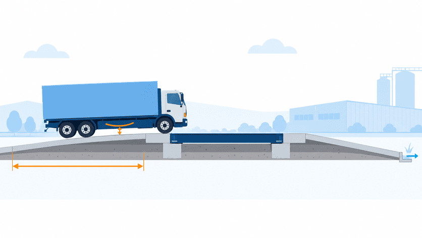
That answer reverses the order most buyers work in. Below I break down the length calculation you can run on your own site plan today, the two clearance geometries that cause bottoming out, why ramp settlement becomes a weighing dispute, and how to write ramp scope into a contract before mobilisation.
Why does weighbridge ramp design start with site length, not slope?
Most of the ramp drawings I review arrive with a slope already written on them and no site dimension beside it. Then the contractor discovers the yard is 6 metres too short. At that point every remaining option costs money or accuracy.
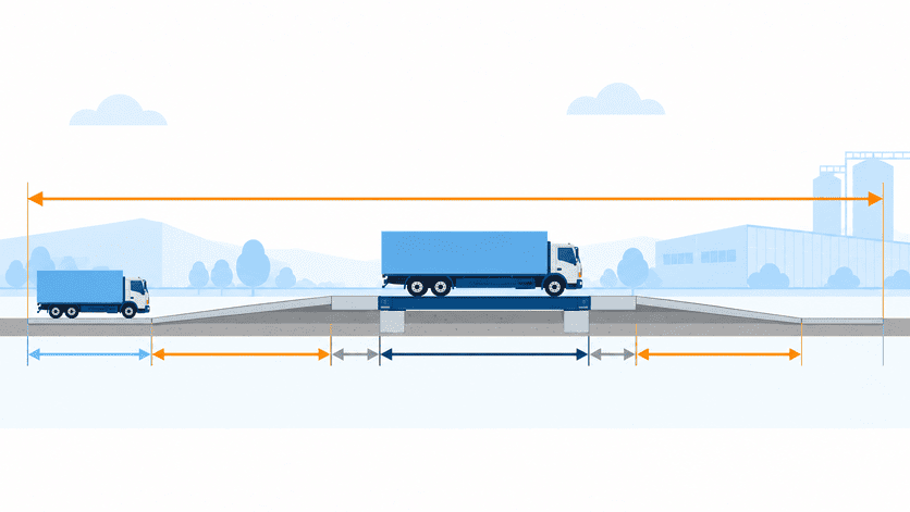
Weighbridge ramp design starts with length because slope is an output, not an input. Usable site length must cover the deck, approach ramps at one or both ends, a level transition zone at each deck end, and queuing space. Once those are fixed, the ramp gradient is whatever remains — and sometimes nothing acceptable remains.
The length budget you can run on your own site plan
I ask for two things before quoting: total usable length and the heaviest, lowest truck that will use the bridge. Here is the arithmetic behind that request.
Total length required = deck length + (ramp length × number of access ends) + (level transition zone × number of access ends) + staging/queuing allowance
Ramp length itself comes from deck height above grade divided by the target gradient:1
| Deck height above grade | Gradient 10% (1:10) | Gradient 8% (1:12.5) | Gradient 6% (1:16.7) |
|---|---|---|---|
| 300 mm | 3.0 m | 3.8 m | 5.0 m |
| 450 mm | 4.5 m | 5.6 m | 7.5 m |
| 600 mm | 6.0 m | 7.5 m | 10.0 m |
Practical planning figures from field experience and common manufacturer installation practice. Confirm against local codes and the project's civil engineer.
So a pitless bridge sitting 450 mm above grade, 18 m deck, drive-through, at an 8% target gradient needs roughly 18 + (5.6 × 2) + (4 × 2) ≈ 37 m before you add any queuing area. That number surprises people.
What to do when the site is short
- Steepen the ramp — cheapest on paper, worst for low-clearance trailers.
- Shorten the deck — risks axle-group overhang and non-compliant weighing for your vehicle mix.2
- Go one-way with reversing — removes one ramp, adds cycle time and reversing risk.3
- Consider a pit or semi-pit layout — reduces or removes ramps, adds excavation and drainage work.
- Relocate the bridge — usually the honest answer when the gap is large.
If the length budget fails, fix the layout. Do not fix it by quietly raising the gradient.
What slope limits does weighbridge ramp design need for the worst vehicle on site?
A yard full of rigid tippers tolerates a gradient that destroys a low-deck container chassis. I have seen a ramp pass acceptance with company trucks and then scrape every third-party trailer that arrived the following month.
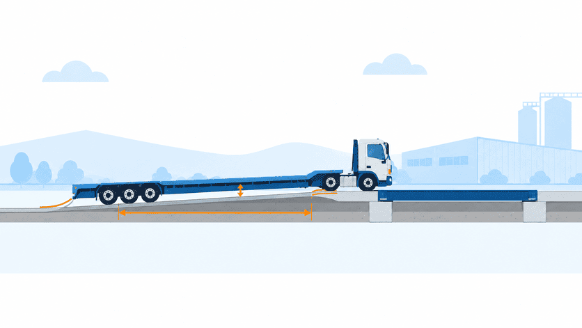
Weighbridge ramp design must be dimensioned for the lowest-clearance and longest-wheelbase vehicle expected, not the average one. Low-deck semi-trailers and container chassis typically need the gentlest gradients, while rigid tippers and mine haulers tolerate steeper approaches. The grade-change rate at the ramp toe and crest matters as much as the average slope.
Practical planning ranges by vehicle class
| Vehicle class | Typical planning gradient | Main constraint | ||
|---|---|---|---|---|
| [ | Low-deck semi-trailers, container chassis | 4–6% | Underbody and kingpin clearance | ](4">https://ops.fhwa.dot.gov/Freight/publications/size_regs_final_rpt/index.htm)4 |
| Standard tractor-trailer combinations | 6–8% | Articulation angle at crest | ||
| Rigid trucks, tippers, agricultural | 8–10% | Load shift, traction when wet | ||
| Mine haulers, heavy off-road plant | Site-specific | Suspension travel, OEM limits |
These are planning ranges drawn from supplier-side field experience, not a regulatory table. National and local requirements vary and need verification for your jurisdiction.
The two failure geometries buyers ignore
1. Underbody clearance at the ramp-to-deck break. The average slope can look mild while the break line at the top of the ramp forms a sharp crest. A long trailer pivots over that crest and the lowest point of its chassis — or the landing legs — contacts the surface.5 This is where bottoming out actually happens.
2. Articulation angle at the toe. When a tractor is still on the ramp and the trailer bogie is on flat ground, the coupling is forced through an angle. Steep ramps with no transition stress the fifth wheel and can lift axles momentarily, which is one cause of unstable readings during roll-on.6
Both failures are controlled by the same fix: a level transition zone. I ask for a flat, paved section at each deck end — in planning terms often around 3–6 m, ideally comparable to a vehicle wheelbase7 — so the grade change is staged rather than abrupt. Curved or stepped grade transitions help further, but the geometry should be signed off by the civil engineer.
How does weighbridge ramp design affect weighing accuracy and settlement?
The most frequent "the scale is wrong" complaint I handle turns out to be a 10 mm step at the deck edge. The scale is fine. The backfill behind the approach slab settled.
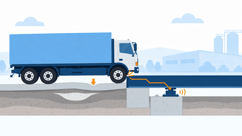
Poor weighbridge ramp design and compaction create a step at the deck-to-ramp joint. Trucks then impact the deck instead of rolling onto it, producing shock loading, unstable readings, accelerated load cell and mount wear, and disputed tickets. Settlement is a civil defect that presents as a metrology failure.
Why settlement hides behind the scale
Ramp approach slabs sit on backfilled ground. Weighbridge foundations are deeper and stiffer. The two settle at different rates.8 If the backfill behind the approach was placed in thick lifts or compacted poorly, it consolidates under loaded traffic within weeks.9 The result is a lip at the joint.
What that lip does:
- Impact loading on the deck end module instead of smooth roll-on.
- Transient overload on the nearest load cells, shortening service life.10
- Reading instability that drivers and shippers read as dishonesty.
- Water pooling at the joint, which attacks the deck edge and, on pit installations, finds its way into the pit.
Drainage sits in the same bucket. A ramp that slopes water toward the foundation turns every rainfall into a corrosion and settlement event.11 I would rather see drainage fall away from the pit and foundation on day one than a dewatering pump added in year two.
Handover acceptance checklist
- Joint level — measure the step at the deck-to-ramp joint across the full width. Specify a tight tolerance (a few millimetres is the practical target) and record the measured values.
- Grade continuity — run a straightedge across the toe and crest; check for abrupt breaks, not just average slope.
- Compaction and backfill records — ask for the contractor's test results. Verify them as documents.
- Drainage test — water poured at the joint should move away from the foundation and pit.
- Loaded re-check — re-measure the joint after the first weeks of loaded traffic. Early settlement shows up fast.
- Re-levelling plan — agree in advance who grinds, shims, or re-pours if a step appears, and under whose warranty.
Write the joint tolerance and the loaded re-check into the handover document. Without them, every later weight dispute becomes a supplier argument.
Who owns the ramp in weighbridge ramp design scope?
The gap I see most often is not technical. It is contractual. The dealer quotes the scale, the client assumes ramps are included, and the civil contractor prices only the foundation. Everyone discovers the gap after mobilisation.
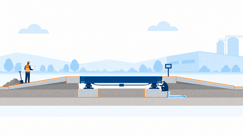
In weighbridge ramp design, the scale manufacturer normally supplies the deck, load cells, junction box, indicator, embedded plates, installation drawings, and load data. The civil contractor normally owns excavation, foundation, approach ramps, backfill, drainage, pavement, and markings.12 Pitless installations do not remove civil work — they move it into the ramps.
Typical scope split
| Item |
References
- To Determine Percent of Slope and Angle of Slope
- NIST Handbook 44: Specifications, Tolerances, and Other ...
- Pedestrian Safety: Prevent Pedestrian Crashes
- Federal Size Regulations for Commercial Motor Vehicles
- Breakover angle
- Comprehensive Truck Size and Weight (TS&W) Study Phase ...
- NIST Handbook 44: Specifications, Tolerances, and Other ...
- Chapter 2. Current Sls Design Procedures and Criteria
- Chapter 8 - NHI-05-037 - Geotech - Bridges & Structures
- A computer vision and dynamic strain fusion approach ... - PMC
- Geotechnical Aspects of Pavements
- State of Oregon - Bid Solicitation - S-73000-00006046